Block Creation In AutoCAD
Last updated:
August 26, 2025
What’s in this article?
This article is a complete how-to on block creation in AutoCAD. You will learn what block creation is, why blocks are useful, step-by-step methods for BLOCK, WBLOCK, and BEDIT, and how to make dynamic and annotative blocks. It covers attributes and data extraction, nested blocks, managing libraries, unit and scale issues, preventing duplication and reducing file size, and common errors with troubleshooting tips. The guide also explains block behavior commands and variables so you can create, edit, share and manage robust AutoCAD block libraries for consistent, efficient drawings and BIM-friendly workflows.
What is Block Creation in AutoCAD?
Block creation in AutoCAD is the process of taking a set of drawing objects and defining them as a single named entity that can be inserted repeatedly. A block encapsulates geometry, text, attributes, and even nested blocks so you can reuse standardized components across drawings. Creating blocks reduces repetitive drafting, enforces standards, and helps maintain consistency across plans, elevations and details. Blocks are stored in the current drawing’s block table and can be saved externally with WBLOCK for sharing. When you insert a block, AutoCAD places a reference that points to the block definition without duplicating the definition itself, which keeps file size and layer management cleaner. Effective block creation includes choosing a proper base point, assigning layers wisely, and deciding whether attributes, parameters, or visibility states are needed for flexibility.
Why use blocks in AutoCAD and what are their benefits?
Blocks are foundational to efficient drafting and project standards in AutoCAD. Using blocks reduces repetitive drawing tasks, ensures consistency, and enables global edits by redefining a single block definition rather than changing many individual symbols. Blocks can store complex assemblies, standard details, titleblocks, and annotation elements so teams can enforce CAD standards and speed up production.
Key benefits include improved file performance because block definitions are stored once and referenced multiple times, easier layering and object control, and the ability to attach attribute data that can be extracted for schedules and BOMs. Blocks facilitate collaboration by allowing teams to share standardized symbols and by supporting external block libraries. They also reduce errors: a corrected block definition propagates changes to all instances, minimizing out-of-date symbols. Blocks support parametric behavior through dynamic blocks, giving flexible geometry without multiplying block definitions.
Other practical advantages include better plotting consistency and simpler management of repetitive geometry in large drawings. With proper naming conventions and library management, blocks become an integral part of a CAD standard that speeds delivery and improves drawing quality.
How do I create a basic block using the BLOCK command?
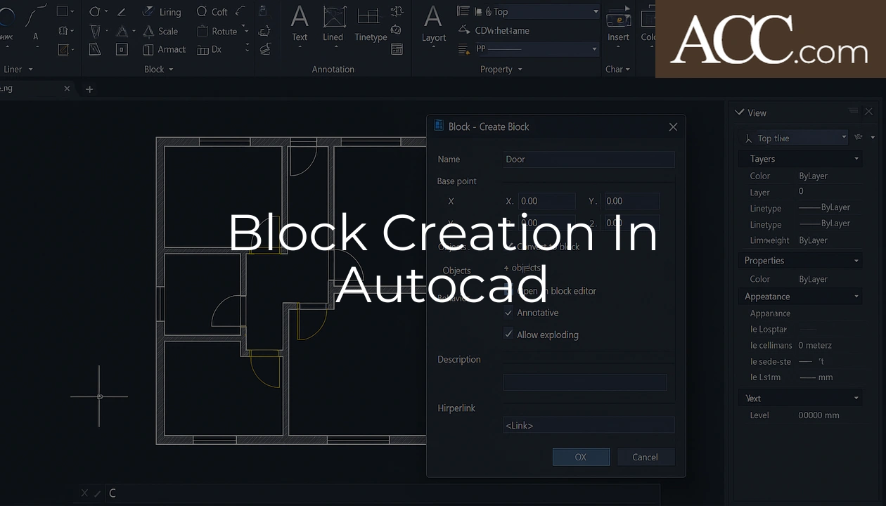
Creating a basic block with the BLOCK command is straightforward and useful for grouping geometry inside the current drawing. Start by selecting the BLOCK command from the ribbon or typing BLOCK at the command line. The Block Definition dialog guides you through naming the block, selecting objects, and setting the base point. The base point is the insertion point for future inserts, so pick a logical location such as a corner or centroid. When you select objects, include only the geometry that belongs to the block; leave reference geometry or construction lines out unless they are intentionally part of the symbol.
After you select objects and the base point, choose whether to convert the selected objects to a block or to leave them in place while creating the block definition. Use the “Delete” or “Retain” option based on whether you need the original geometry left in the model. If layers and properties need to be preserved, ensure the objects are set up correctly before creating the block. You can also choose to open the block in the Block Editor for more complex edits if necessary.
- Type BLOCK or select Create Block from the ribbon
- Give the block a meaningful name following your CAD standard
- Pick a precise base point for insertion control
- Select the objects you want to include and choose Retain or Delete
After creating the block, test it by using the INSERT command or the tool palette to place instances. Check that the block scales and rotates as expected and that attributes (if any) behave correctly. If you see issues, reopen the definition with BEDIT to adjust geometry, layer assignments, or the base point. For a more portable block that can be reused in other drawings, use WBLOCK to write it to an external DWG file (covered later). Naming, base point, layer usage and attribute planning at creation time will save rework later and keep your block library manageable.
How do I create a block using the WBLOCK command and when should I use it?
WBLOCK creates an external DWG file from selected objects or from a block definition. Use WBLOCK when you want to export a block as a standalone file for sharing, building a standard library, or moving content between projects without bringing unnecessary drawing data. To use WBLOCK, type WBLOCK at the command line or choose Write Block from the application menu. In the dialog, you can select source: Objects, Block (choose a block name in the current drawing), or Entire drawing. If you choose Objects, pick the geometry and specify a base point that becomes the insertion point for other drawings.
When exporting from a block name, WBLOCK writes only that block definition (and nested definitions required) to the target DWG, preserving layers and attributes. This is ideal when creating a symbol library: save each symbol as its own DWG in a structured folder system. Use clear naming conventions and folder hierarchies to make the library accessible via DesignCenter or tool palettes. If the source drawing contains many layers or styles you do not want to export, prepare a clean source drawing or use block isolation techniques first.
WBLOCK is necessary when sharing blocks across teams or linking to external references because it creates a portable, standalone file. When importing a WBLOCK into another drawing using INSERT or DesignCenter, AutoCAD treats the DWG as a block definition. For automations and batch library creation, WBLOCK can be scripted or used with LISP routines to export many blocks at once. Always check units and scale before exporting: WBLOCK preserves the source units and coordinates, so verify base points and measurement units to avoid scaling issues on insertion in other drawings.
How do I edit an existing block using the Block Editor (BEDIT)?
The Block Editor (BEDIT) lets you edit the definition of a block in a focused environment. To start, type BEDIT or pick Edit Block from the ribbon. Choose the block you want to modify from the list; AutoCAD opens the Block Editor with the block’s components displayed in a temporary editing space. This isolates the block geometry from the rest of the drawing and gives access to contextual tools like parameter and action palettes for dynamic blocks. Changes you make in BEDIT affect all instances of that block once you save the definition and exit the editor.
Inside the Block Editor, you can add or remove geometry, change layer assignments, adjust attribute definitions, and modify parameters or visibility states if the block is dynamic. Use grips, commands, and grips-enabled tools to edit precisely. Keep these tips in mind:
Always work with the correct block units and coordinate system in the Block Editor. If the block was created with a base point offset or nested transformations, consider displaying the UCS or using temporary tracking for alignment. Use the Properties palette to edit layer, linetype, color, and annotation settings within the block. If your block contains attributes, you can edit the attribute definitions (not the instance values) in BEDIT so that future inserts carry updated prompts and default values.
After finishing edits, click Save Block to store changes to the block definition. If you want to preview how changes affect existing instances, use the Test Block feature (available in the Block Editor) or simply exit and inspect inserted instances. If you need to change a block name or replace it with a different definition, close BEDIT and use the Rename or Insert/Replace workflows in the drawing. Remember that editing a block that is referenced in many layouts or active xrefs can have broad effects, so coordinate with collaborators and use version control if possible.
What are dynamic blocks and how do I create them?
Dynamic blocks introduce parameters and actions into a block definition so a single block can behave like multiple variants without creating numerous separate block definitions. Parameters define measurable or selectable aspects — for example, linear parameters let you stretch or resize parts, and alignment or rotation parameters control orientation. Actions are verbs attached to parameters: Stretch, Move, Rotate, Scale, Array, and Visibility actions are common. Visibility states let you switch between predefined arrangements of the same geometry, such as plumbing fixture orientations or furniture configurations.
To create a dynamic block, begin by opening the block definition in the Block Editor (BEDIT) and add parameters from the Block Authoring palette. A typical workflow:
1. Create or open the base geometry in the Block Editor. 2. Add parameters that reflect the ways users will change the block (linear, rotation, etc.). 3. Attach actions to parameters where behavior is required (a Linear parameter with a Stretch action to lengthen a sign, for example). 4. Add grips if you want quick in-drawing handles. 5. Define visibility states and create geometry for each state, then assign the Visibility parameter to control which geometry is displayed. 6. Test the dynamic behaviors inside the editor with the Test Block tool until they work reliably.
Design the dynamic interface with users in mind: minimize the number of parameters and provide intuitive grips. Overly complex dynamic blocks are harder to use and maintain. Use constraints sparingly; while geometric constraints can add stability, they increase complexity and can conflict with actions. For example, use a linear parameter for length and limit it with visibility or lookup tables if only certain lengths are valid.
Use visibility states for orthogonal alternatives or component toggles:
- Door symbol with left/right swing
- Fixture with different mount types
- Titleblock with optional logo rows
Advanced techniques include using Lookup parameters to present a list of preset configurations, or combining Array actions with polar parameters to create rotating fan arrays. Always test dynamic blocks in real drawing contexts to ensure performance and usability. Keep dynamic blocks documented in your CAD standard (describe available grips, parameters and recommended insertion workflows) so other users can exploit their flexibility without needing to reverse-engineer behavior.
How do I add attributes to blocks and extract attribute data?
Attributes are text-based data fields embedded in block definitions that hold metadata such as part numbers, descriptions, sizes, or supplier info. To add attributes, open the block definition in BEDIT or create them when you define the block with the ATTDEF (Attribute Definition) command. In the ATTDEF dialog specify tag, prompt, default value, text style, height, justification and layer. Pick an insertion point for the attribute inside the block geometry and consider using visibility or annotation features so attribute text scales or hides appropriately at different scales.
Use clear attribute naming conventions (TAG values) that align with your data extraction templates and external databases. Tags should be uppercase, brief, and unique within your block library to avoid confusion during extraction. Also plan which attributes are editable at insertion time and which should remain constant; you can set attributes to invisible if they are only for data extraction and shouldn’t clutter the drawing.
To extract attribute data, use the Data Extraction wizard (DATAEXTRACTION command) or the older EATTEXT/ATTEXT tools. The Data Extraction wizard walks you through selecting the source (current drawing or multiple drawings), choosing objects or blocks to include, selecting attribute tags to extract, and formatting the output. Data Extraction supports exporting to CSV, Microsoft Excel, or inserting the extracted table directly into the drawing. Map attribute tags to columns for schedules and bills of materials. For ongoing workflows, save the extraction template (.dxe) so repetitions are fast and consistent.
Automating attribute population can be done via scripts, AutoLISP, or linking attributes to external databases via OLE, DAta Link, or third-party tools. When attributes are used in schedule-producing workflows, keep tag consistency and unit formatting in mind. Also be careful with nested blocks: Attribute extraction can include attributes from nested block levels if you select recursive options. Finally, protect attribute definitions by locking blocks or training staff on correct attribute editing procedures to maintain reliable extraction results.
What is the difference between blocks, groups, and xrefs?
Blocks, groups, and xrefs are all methods of organizing reusable content in AutoCAD but they serve different purposes. Blocks create named definitions within a drawing and are best for creating reusable symbols and assemblies. Groups are simple collections of objects that behave as a single selection set but do not create a named, reusable definition in the block table. Xrefs (external references) attach entire drawings as overlayed references that remain separate files and can be updated independently. Understanding these differences helps decide the proper tool for each situation.
| Feature | Block | Group | Xref |
|---|---|---|---|
| Definition stored | Inside drawing block table | Not a separate definition | In external DWG file |
| Reuse across files | Yes, via WBLOCK or DesignCenter | No | Yes, by referencing DWG |
| Best for | Symbols, parts, attributes | Temporary selection sets | Large assemblies, backgrounds, site plans |
Choose blocks for standardized symbols, groups for short-term selection convenience, and xrefs for managing large or commonly shared drawings such as base plans or consultant models.
How do I scale, rotate, mirror, and insert blocks correctly?
When inserting blocks, use the INSERT command, the tool palettes, or DesignCenter. Choose insertion point, scale, and rotation at the prompt. For precise control use object snaps and the base point chosen during block creation. If you want uniformly scaled instances, use the same scale factor for X, Y and Z (or lock scaling via properties) to avoid distortion. When rotating inserts, provide rotation angles numerically or by picking points; avoid making rotation part of the block definition unless it’s intended.
Use the SCALE and ROTATE commands on block references when you need to change only particular instances. Be aware that exploding a block before transforming it will break the block relationship and create individual geometry. Mirroring a block can change block handedness — if the block contains attributes, mirrored instances may remain references to the same definition but attribute alignment can be affected. For dynamic blocks, prefer using provided grips or parameters for resizing and rotating so you preserve dynamic behavior. Disable annotative scaling or change annotation properties if text or annotation changes unexpectedly when scaling blocks.
How do base point and insertion point affect blocks?
The base point (also called insertion point) determines where a block anchors when inserted or moved. Choosing the correct base point makes alignment, snapping and assembly placement predictable. If you set a base point at a corner, you can snap to that corner when inserting; if you set it at the center, you can quickly center objects. When editing a block with BEDIT, you can change the base point using the Base Point command or redefine the block so the new base is used for subsequent inserts. Misplaced base points lead to frustrating alignment issues, so decide base points with common insertion workflows in mind.
How do I create annotative blocks and control annotation scale?
Annotative blocks automatically adjust their display size to match the drawing’s annotation scale, which is essential for text, symbols and dimensions that must appear consistent across viewports and paper space. To create an annotative block, make sure the objects inside use annotative text styles, dimensions or blocks. When defining the block, set the block definition to be annotative by checking the Annotative option in the Block Definition dialog or by using the BLOCK command and toggling annotative. You can also convert an existing block to annotative by redefining it in BEDIT and enabling annotation scaling.
After creating an annotative block, control its scale through the drawing’s annotation scales list. Insert the block and then use Properties or right-click options to add or remove annotation scales for that block reference. When a block has multiple annotation scales assigned, AutoCAD will display the instance at the appropriate size when the drawing view’s annotation scale matches one of the assigned scales. In paper space, viewport scale determines which annotative representation is shown. If a block’s annotation scale is incorrect, check text styles, dimension styles, and the block’s annotative flag, and reassign the required scales. For multi-scale presentations, supply the block with representative annotation sizes or use visibility states to hide or show scaled variants.
How do I manage block libraries with DesignCenter and Tool Palettes?
DesignCenter and Tool Palettes are primary tools for managing block libraries. DesignCenter (ADCENTER) lets you browse directories and open DWG files to access block definitions and drag them into the current drawing. Use DesignCenter to preview blocks before insertion and to maintain a consistent folder structure for libraries. Tool Palettes allow you to create drag-and-drop block tools with predefined insertion point, scale, layer and attribute properties. Save frequently used symbols to tool palettes so team members can insert them with a single click.
Organize libraries with clear folder hierarchies and naming conventions. Use WBLOCK to export block files into a centralized library and then use DesignCenter to link those files. Synchronize tool palettes across workstations by exporting and importing the .xtp file or using company network locations for shared palettes. Document palette contents and recommended usage in your CAD standard. When changes are required, update the source DWG and re-publish the palette item so all users access the latest version. For large organizations, consider a version-controlled library and standard operating procedures for submitting and approving new blocks.
How do I convert geometry to a block or explode a block?
Convert geometry to a block by selecting objects and using the BLOCK command or by using WBLOCK to export selected objects. Be mindful of layer assignments and object properties before conversion because they are preserved in the block definition. To break a block into its constituent objects, use the EXPLODE command. Exploding a block removes the block relationship and produces raw geometry; nested blocks may require repeated explode operations. Avoid exploding blocks in production drawings unless necessary because it disrupts the block’s reusability and can increase file size and maintenance effort. If you need to edit a block’s geometry, prefer using BEDIT to preserve the block definition and instance links.
How do I manage nested blocks and block nesting best practices?
Nested blocks are blocks that contain other blocks inside their definitions. They are useful for assembling complex symbols from reusable subcomponents, but they add complexity to editing, attribute extraction and file management. Use nesting to keep consistent subcomponents (for example, fasteners or text frames) and to avoid duplicating definitions. However, limit nesting depth to reduce confusion; deep nesting makes it harder to locate definitions and to update individual subcomponents.
Best practices for nesting include:
- Keep subcomponent blocks generic and well-named
- Avoid unnecessary nesting for simple symbols
- Document nesting hierarchy in your CAD standard
When extracting attributes or exporting WBLOCKs, be mindful that nested blocks may bring implicit definitions into the exported file. Use the DesignCenter or BATTMAN utilities to inspect nested definitions and manage them. For editing, you can open nested block definitions directly in BEDIT by selecting the nested block name. Also be careful with layer naming conventions; nested blocks may include layers that overlap with host drawing layers—use layer naming conventions or prefixed layer names for library content to minimize collisions. If performance becomes an issue, consider flattening some nested components into a single block where flexibility is less important.
How do I rename, redefine, or replace blocks globally?
To rename a block, use the RENAME command and select Blocks from the list. Renaming updates the definition name but keeps references intact. To redefine a block globally, edit the block in BEDIT and save changes; all instances update immediately. If you need to replace a block with another definition (for example, swapping a temporary symbol for a standard one), use the -INSERT and -BLOCK commands or manually INSERT the desired block and use the BLOCK command with the same name to redefine it, or use the “Replace Block” feature available via context menus or third-party utilities. For batch replacement across multiple drawings, use scripts, AutoLISP, or the DesignCenter to drag a block into multiple open drawings.
How do I prevent block duplication and reduce file size?
Block duplication occurs when identical or slightly modified copies of symbols proliferate in a project. Prevent this by centralizing libraries, using standardized names, and training users to reuse existing blocks through DesignCenter and tool palettes. Regularly clean drawings with PURGE to remove unused block definitions, layers, styles and linetypes. Use the -PURGE command for scripted purging operations when needed. Replace duplicate block definitions with a single canonical block and use the RENAME utility to normalize names.
To reduce file size, prefer blocks over copied geometry since references store only one definition. WBLOCK can be used to create compact external files for frequently used symbols. Use PURGE and the OVERKILL command to remove overlapping or redundant geometry. Audit drawings with the AUDIT command to fix inconsistencies and use the -EXPORTTOAUTOCAD or DWGSHARE practices for compatibility with older formats when necessary. Also check for unnecessary xrefs, embedded images, or complex hatches that may inflate file size and manage them separately.
How do I handle unit and scale issues when inserting blocks from different drawings?
Unit and scale problems arise when block definitions originate from drawings with different units or scales. AutoCAD stores unit information in the drawing’s settings but block definitions don’t carry an explicit “units tag” in older versions, so consistency is critical. When inserting a DWG as a block via INSERT or DesignCenter, use the dialog options to scale units automatically if available, or manually calculate scale factors. Before exporting blocks with WBLOCK, ensure the source drawing’s units and base point are suitable for target drawings.
To avoid problems, standardize on drawing units across your office or provide a checklist for block creation: verify units, set a logical base point, and test insertion in a template drawing. If you must insert blocks from a metric drawing into an imperial project, compute and apply the correct scale factor on insertion (e.g., 25.4 for mm to inch conversions or 0.03937 the other way). Consider keeping separate metric and imperial libraries to simplify workflows and avoid accidental mis-scaled insertions.
How do I share blocks between projects and create standard block libraries?
Share blocks by exporting them as DWG files with WBLOCK and storing them in a centralized network library or a cloud storage location with consistent folder structure. Use DesignCenter and Tool Palettes to allow quick access: point DesignCenter to the shared folders and publish tool palettes pointing at the canonical library. For enterprise setups, maintain version control and a process for adding and approving new blocks to the standard library. Document naming conventions, base point standards, layer handling, and attribute tag rules so new blocks comply with the CAD standard.
What are common errors when creating blocks and how do I troubleshoot them?
Common block creation errors include wrong base point placement, incorrect attribute tags, unintended layers or linetypes embedded, unexpected behavior from dynamic parameters, and scale/unit mismatches. Troubleshoot systematically: first inspect the block definition with BEDIT to confirm geometry, layer assignments, and attribute definitions. If attributes don’t populate correctly, check attribute tag names, case sensitivity and default values. When instances display incorrectly, verify annotative flags, text and dimension styles, and assigned annotation scales.
If a block causes performance issues or behaves unpredictably, run PURGE and AUDIT on the drawing and examine nested definitions for bloated or duplicated content. Use the LIST or PROPERTIES to inspect a block reference’s scale and rotation values. For unit problems, test inserting the block into a clean template drawing with known units to detect systematic scale differences. When dynamic block parameters fail, re-open the editor and use the Test Block tool; confirm that actions are correctly attached to parameters and that any constraints do not conflict with actions.
When block definitions differ across team members, synchronize libraries and enforce naming conventions. If xrefs and blocks interact poorly, consider binding xrefs or replacing xref contents with proper blocks after coordination. For stubborn issues, export the block with WBLOCK to a fresh drawing, rebuild the definition, and re-import it; this often removes hidden corruptions and cleans up style references. Keep a log of fixes and update your CAD standard to prevent repeat errors.
How do I create visibility states, parameters, and actions in dynamic blocks?
Creating visibility states, parameters, and actions is central to making useful dynamic blocks. Start in the Block Editor (BEDIT) and open the Block Authoring palette. Add a Visibility Parameter from the palette and create new Visibility States with descriptive names for each variant (for example, Open, Closed, Left, Right). For each visibility state, turn on or off the geometry appropriate to that state; AutoCAD retains the visibility assignments for each state. Use the Visibility Parameter to control which geometry is shown at insertion and to allow quick switching via the Properties palette or grips.
Parameters measure or define control points. Common parameters include Linear, Rotation, Flip, Point, XY, and Lookup. Add a parameter and set its limits or base location. Then attach Actions to parameters — for instance, attach a Stretch (an action) to a Linear parameter to allow a user to drag a grip and stretch part of the block. Move actions attached to Point parameters let components translate relative to the base point. Rotate actions attached to Rotation parameters provide instance-level rotation without altering the overall block reference rotate value.
Link parameters and actions carefully. For example, to create a door symbol that can flip left/right and change width:
- Add a Visibility parameter for left and right swing states
- Add a Linear parameter controlling the door leaf width
- Attach a Stretch action to the Linear parameter, ensuring the action’s stretch frame includes only the movable geometry
- Use Flip parameters for mirroring when geometric reversal is needed
Use Lookup parameters for preset combinations: create named entries (e.g., 600mm, 900mm, 1200mm) and map parameter values to those entries so users can pick standard sizes quickly. When designing actions, define precise selection sets for each action to avoid accidental transformation of unrelated geometry. Test each state and action using the Test Block feature. Keep parameter counts minimal for usability: too many parameters or nested dependencies lead to unpredictable interactions. Provide clear naming and documentation of parameters and visibility states so users understand the available options and grips. Finally, validate dynamic blocks across viewports and annotation scales to ensure good behavior in both model and paper space.
How do attributes link to external databases and how do I use Data Extraction?
Attributes can be linked to external databases to automate data population and to synchronize CAD elements with project or asset management systems. You can use AutoCAD’s Data Link Manager to attach an Excel spreadsheet or ODBC connection and then use field expressions or scripts to populate attribute values. Alternatively, third-party plugins facilitate direct linkage between block attributes and databases (SQL, Access, or other systems) to pull part numbers, descriptions, costs, and lifecycle data.
Data Extraction (DATAEXTRACTION) is the core AutoCAD feature for harvesting attribute data across one or many drawings. The Data Extraction wizard guides you through creating an extraction: choose the source drawings, select which block definitions and attribute tags to include, filter results, and format output. You can export to CSV, Microsoft Excel, or create a table within the drawing. Save the extraction template (.dxe) to reproduce the same extract across multiple project stages. When preparing extractions, ensure attribute tags are consistent and that nested block attributes are included if needed. Use the mapping and formatting steps in the wizard to convert raw attribute values into usable schedule fields and to include computed columns, such as quantities or concatenated descriptions.
For database synchronization workflows, consider exporting attribute data to Excel, performing reconciliations, and importing back updates via scripts or Data Links. Some firms use automated tools that match block tags to database fields and push updates back to the drawing, but always maintain a backup before bulk imports to prevent accidental overwrites. Finally, document your attribute tagging standard and data extraction templates so team members can run repeatable, auditable schedules and BOMs.
What AutoCAD commands and system variables most affect block behavior?
Several commands and system variables directly influence how blocks behave. Key commands include BLOCK, WBLOCK, BEDIT, ATTDEF, INSERT, EXPLODE, RENAME, PURGE, and DATAEXTRACTION. Keep these tools in your workflow for creating, exporting, editing, cleaning and extracting block content. Dynamic block authoring uses PARAMETERCURSOR, BATTMAN helps manage attributes, and DesignCenter (ADCENTER) aids library access.
Important system variables include:
- ATTDIA — controls attribute editing dialog behavior
- INSERTUNIT — affects unit scaling when inserting external blocks
- CLAYER and BLOMASK — control layer behavior and block masking
- ANNOALLVISIBLE — influences annotative display
- BLOCKWISEROW — impacts some listing and batch operations
Also monitor DIMASSOC and TEXTFILL when blocks contain annotations. Understanding these commands and variables helps you predict and control block insertion, scaling, annotation behavior, attribute handling and global edits. For production environments, document preferred settings and include them in template drawings to maintain consistent block behavior across users and projects.
